Quick Cart
Subtotal: $0.00
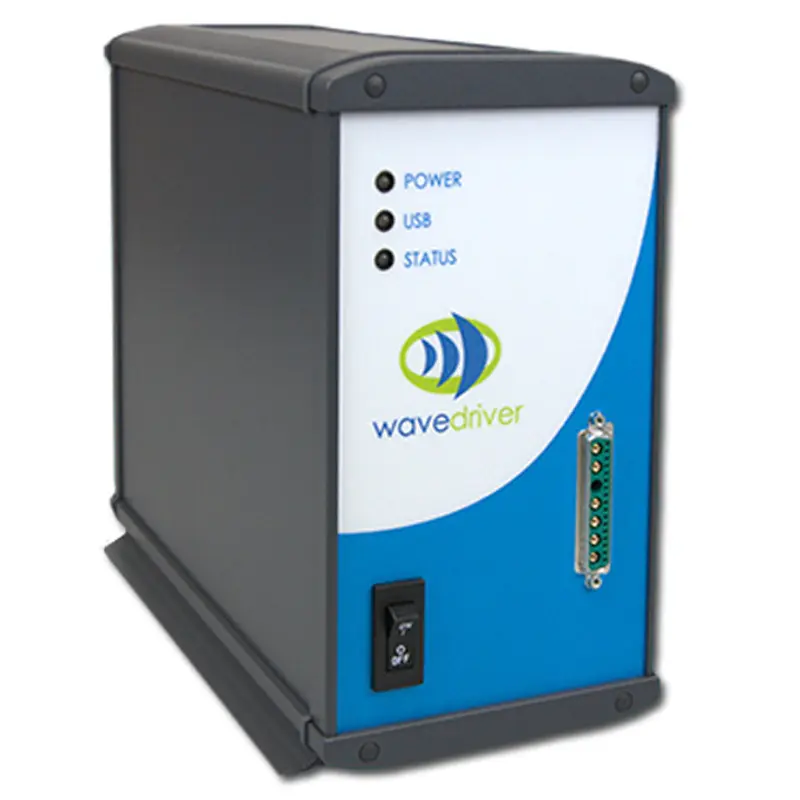
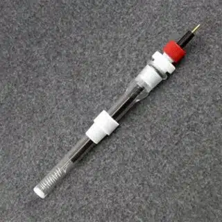
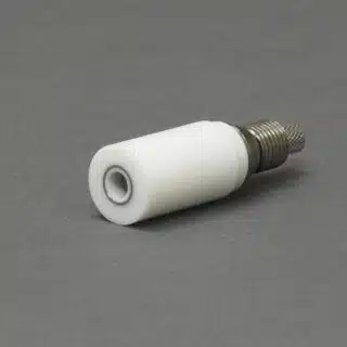
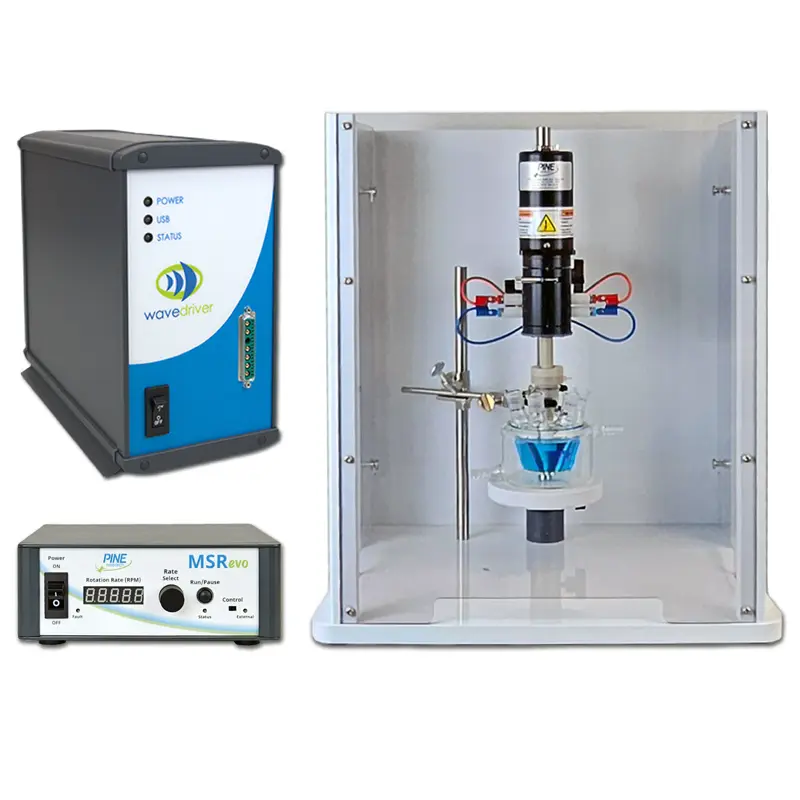
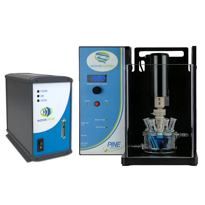
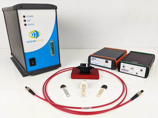
This WaveDriver® 40 Workstation is an affordable bipotentiostat/galvanostat, dual-electrode electrochemical workstation available in a variety of configurations. Under the control of our powerful AfterMath® Blue software package, the WaveDriver 40 Workstation is capable of performing a wide range of single and dual electrode DC electroanalytical techniques. The WaveDriver 40 features a true integrated bipotentiostat, capable of controlling one or two working electrodes operating in the same electrochemical cell along with a counter and reference electrode, making this instrument ideal for Rotating Ring-Disk Electrode (RRDE) voltammetry.
This product can only be purchased in bundles. View these related bundles in the tab below.
Customers must be logged into their account to view prices. Not all regions provide pricing online. If you do not see prices, you can obtain them from the designated sales channel in your region.