WaveDriver 100 Electrochemical Workstation

Part Number
AFP5

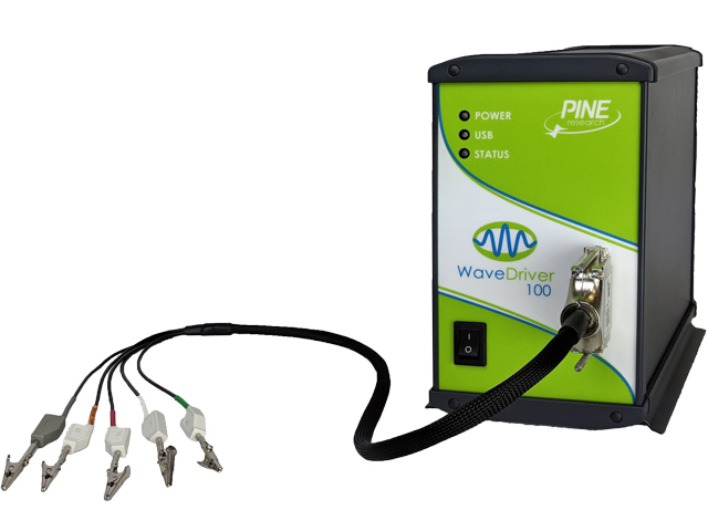
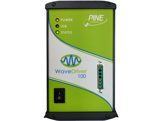
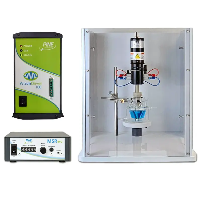
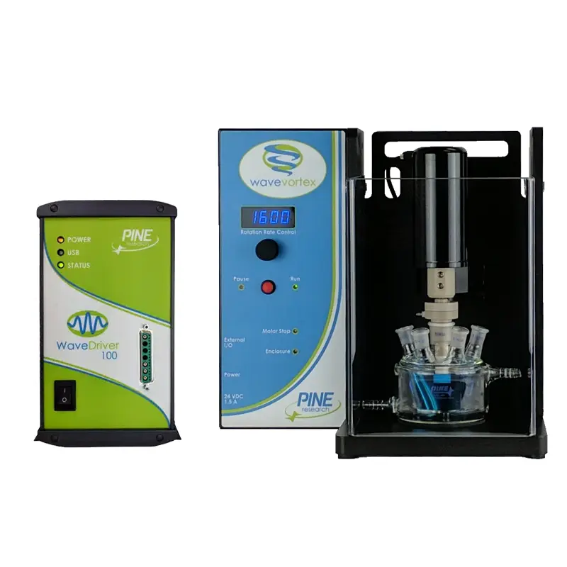
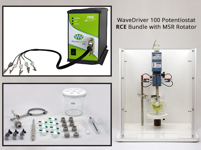
This WaveDriver® series electrochemical workstation is a robust single-channel system capable of potentiostatic, galvanostatic, and EIS experiments. Under the control of our powerful AfterMath Blue® software package, the WaveDriver 100 electrochemical workstation is capable of performing Electrochemical Impedance Spectroscopy (EIS) along with a wide variety of DC electroanalytical techniques. The WaveDriver 100 is ideal for everyday EIS experiments, cyclic voltammetry, differential pulse and square wave voltammetry, and hydrodynamic methods such as Rotating Disk Electrode (RDE) and Rotating Cylinder Electrode (RCE) voltammetry.

Includes Free Training Session!
Every purchase of a WaveDriver 100 electrochemical workstation includes a free one-hour online training session! Contact Pine Research to inquire about this free session.
Tip: Product Similarity
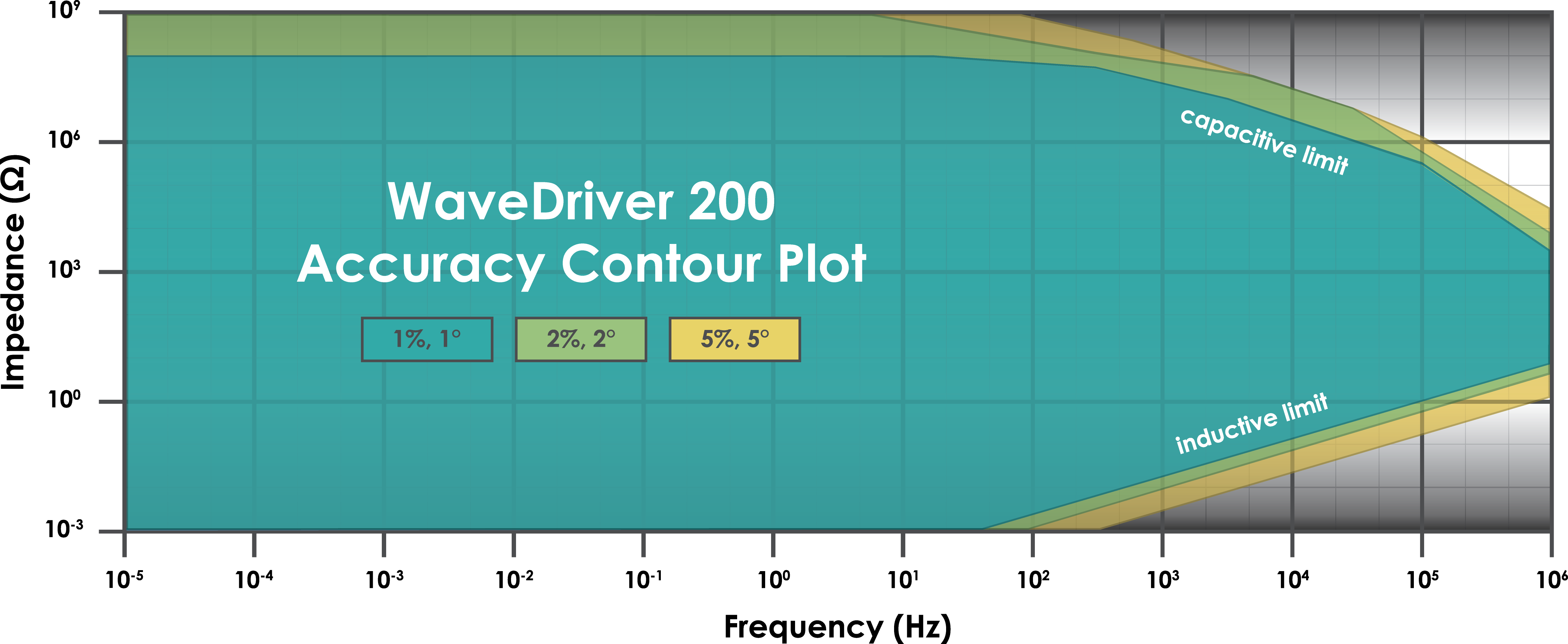
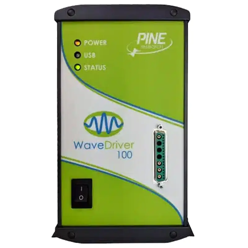
The WaveDriver 100 is a single channel electrochemical workstation with EIS, whereas the WaveDriver 200 is a two-channel bipotentiostat electrochemical workstation with EIS. The WaveDriver 40 does not have EIS, and is a two-channel bipotentiostat. Other specifications are shared among all current models of the WaveDriver Series.

The WaveDriver 100 Electrochemical Workstation has been engineered to provide you with the essential hardware and software features you need at an affordable price. This complete electrochemical workstation offered by Pine Research allows you to perform a full range of traditional DC electroanalytical techniques as well as Electrochemical Impedance Spectroscopy (EIS).

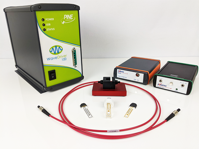
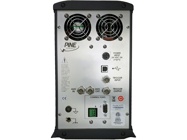
Applications. The WaveDriver 100 finds use in academic and industrial research laboratories around the world and across a wide variety of applications. The instrument offers a large range of accessible current ranges (±100 nA up to ±1 A) and potential ranges (±2.5V up to ±15 V) along with advanced filtering and iR compensation. Back panel connections allow rotation rate control when performing voltammetry using a Rotating Disk Electrode (RDE) or Rotating Cylinder Electrode (RCE). Additional input/output and timing connections permit the WaveDriver to control third-party instrumentation in applications such as spectroelectrochemistry.

Electrochemical Impedance Spectroscopy. Our talented team of engineers and chemists have taken a careful approach to integrating EIS into our WaveDriver series electrochemical workstations, giving you access to the most practical range of EIS frequencies (10 µHz to 1 MHz) at an affordable price. We have incorporated powerful and easy-to-use EIS equivalent circuit fitting directly into our AfterMath Blue software platform. Multiple curve fitting algorithms and options allow you to fit even the most troublesome EIS data to one of the built-in equivalent circuit models, or alternately, you can design and draw your own equivalent circuit model.

Integrated Curve Fitting and Analysis. Our software team has seamlessly integrated EIS curve fitting into AfterMath Blue. Why work with more than one software application to fit your EIS data when you can do it using the very same software application that acquired the data? AfterMath Blue EIS curve fitting utilities provide several analyses, including Circuit Fit, Transmission Line, and Kramers-Kronig. Unlike others, our fitting software also provides several fitting methods including Modified Levenberg-Marquardt (LM), Simplex, and Powell algorithms in addition to fitting options that include dynamic point selection, unity, and parametric fitting.

Novel Transmission Line Fitting. AfterMath Blue provides a unique approach to model your porous electrodes. While the transmission line model is not new, AfterMath Blue provides you with some unique transmission line fitting tools. Instead of a static circuit, where you have no control over the elements of the model, we provide a very flexible basic model, from which you can customize nearly all aspects of the model to suit your system. Give it a try – import your three- or five-column EIS data directly into AfterMath Blue and see the difference with our transmission line fitting.

Finishing Touches. While fitting your EIS data, why flip back and forth between Nyquist and Bode plots? Why not be able to view both plots and fits simultaneously? We heard this feedback from many customers and have designed AfterMath Blue to provide you with both plots simultaneously during fitting. Unique slider controls allow you to rapidly vary the value of one circuit component while watching the effect of that component on the Bode and Nyquist plots.

Electrode Connections
Counter electrode
Drive line with grounded shield
Reference electrode
Sense line with driven shield
Working electrode #1 (WK1)
Separate sense and drive lines, each with driven shield (current measurement via passive shunt)
Working electrode #2 (WK2)
N/A
Working electrode channels
Measured Current
AC accuracy
Frequency- and range-dependent to 1 MHz
AC leakage current
Frequency- and range-dependent to 1 MHz
ADC input
16 bits
Autoranging
Yes
Current ranges (measured and applied)
DC accuracy (measured and applied)
±0.2% of setting; ±0.05% of range
Filters (for DC Experiments)
1 kHz, 10 Hz, 100 Hz, 100 kHz, 30 Hz
Practical current range
20 pA to 1 A
Current Resolution at each range (applied and measured)
3.13 nA, 3.13 pA, 3.13 µA, 31.3 nA, 31.3 pA, 31.3 µA, 313 nA, 313 pA
Applied Current (Galvanostatic Mode)
DAC output
16 bits
Power Amplifier (Counter Electrode Amplifier)
Bandwidth
>2.5 MHz (on fastest speed setting)
Compliance voltage
Noise and ripple
<35 µV RMS in 2 MHz bandwidth
Output current
±1 A (maximum)
Short circuit current limit
10 mA - 100 nA ranges: <200 mA, 1A, 100 mA ranges: <1.3 A
Slew rate/rise time
10 V/µs (on fastest speed setting)
Electrometer (Reference Electrode Amplifier)
CMRR
>100 dB, 0 - 1 kHz, >74 dB at 10 kHz
Electrometer bandwidth
>15 MHz (3 dB)
Input current
<10 pA leakage/bias current at 25°C
Input impedance
>10¹³ in parallel with <10 pF
Measured Potential
Measured potential resolution (at each range)
313 µV per ADC bit, 469 µV per ADC bit, 78 µV per ADC bit
Potential ranges (measured and applied)
Applied Potential (Potentiostatic Mode)
Applied potential resolution (at each range)
313 µV per DAC bit, 469 µV per DAC bit, 78 µV per DAC bit
CV sweep rate (maximum)
CV sweep rate (minimum)
Data Acquisition (for DC Experiments)
Clock resolution
10 ns (minimum time base)
Point interval
Raw point total
<10 million per experiment
Synchronization
Simultaneous sampling of all analog input signals
Ground Connections
Chassis terminal
The instrument chassis terminal is accessible via a banana binding post (metal) on the back panel. The GRAY banana plug on the cell cable also provides a chassis connection.
DC common (signal)
The DC Common is isolated from the USB port, the instrument chassis and earth ground. The DC Common is accessible via a banana binding post (black) on the back panel.
Earth
No direct connection to earth ground is provided.
Impedance (EIS)
Current excitation setpoint
0.01% - 100% of current range, 10% of setting, 200 mA maximum
EIS accuracy
EIS Accuracy Contour Plot
EIS capable
EIS frequency range
EIS frequency resolution
<1 ppm 1 MHz - 100 mHz, <70 ppm 1 mHz - 10 µHz, <80 ppm 100 mHz - 10 mHz, <90 ppm 10 mHz - 1 mHz
EIS frequency stability
±10 ppm
Frequency sweeping
Custom list, Linear, Logarithmic
Modes
Galvanostatic, Potentiostatic
Voltage excitation setpoint
1 mV - 200 mV peak, ±10% of setting
Rotator Control Connections
Digital enable signal
Open drain with 4.7 kΩ pull up to +5 V (TTL compatible)
Rate control signal
±10 V, ±2.5 V
Rotator connector A
7-pin mini circular DIN includes analog and digital signal grounds, digital rotator enable signal (+15 V max), auxiliary digital output signal, and analog rotation rate control signal
Rotator connector B
3-pin connector includes analog signal ground, digital rotator enable signal (+15 V max), and analog rotation rate control signal
Accessories
Cell cable
Combination D-SUB connector to multiple banana plugs via shielded coaxial cables (included)
Dummy cell
External dummy cell included
Auxiliary Connections
Auxiliary analog input
BNC female, ±10 V differential input, 313 µV resolution, 0.2% accuracy (available when second working electrode not in use)
Auxiliary analog output
BNC female, ±10 V bipolar output, 313 µV resolution, 0.2% accuracy (available when second working electrode not in use)
Connector C
9-pin DSUB connector that includes DC Common, two digital output signals, and two digital input signals
Current (I1) output
N/A
Current (I2) output
N/A
Potential (E1) output
N/A
Potential (E2) output
N/A
Trigger input
BNC female, TTL compatible
Trigger output
BNC female, TTL compatible
WK1 input
N/A
WK2 input
N/A
General Specifications
Humidity range
80% RH maximum, non-condensing
Instrument dimensions
160 × 324 × 255 mm (6.3 × 12.75 × 10.0 in)
Instrument weight
4.6 kg (10.2 lb)
LED indicators
Power, USB, and status
Power cord
Various international cables sold separately (C13 type)
Power input
24 VDC (±5%), 5.0 A (low voltage DC device)
Power supply input
100 - 240 VAC, 1.4 - 0.7 A, 50 - 60 Hz
Power supply output
24 VDC, 5.0 A power supply (included) has a C14 type input connector
Shipping dimensions
254 × 356 × 457 mm (10 × 14 × 18 in)
Shipping weight
7.7 kg (17 lb)
Temperature range
10°C - 40°C
Communication
Interface
Wireless capable
Document #
Title
Type
View
Download
DRU10243
WaveDriver 100 Electrochemical Workstation User Guide

Related Products and Accessories

Visit our YouTube channel for helpful instructional videos regarding the use and maintenance of this and many other Pine Research products!