[call_to_action color = “blue”]
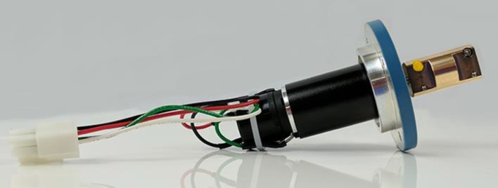
The MSR rotator has a motor controller which is connected to the motor unit via a motor cable.
Related Links: MSR Rotator
[/call_to_action]Earlier versions of the MSR rotator (such as the AFMSRX and AFMSRXE) connected to a round black connector on top of the motor unit. There were a total of four pins in this connector. One pair of pins provided power to the motor, and the other pair of pins provided the rotation rate signal from the tachometer.
If you remove the cowling from the motor unit and inspect the cables connected to the motor and tachometer, you will see four cables with different colors. The signals in each cable are described in the table below.

|
|
| wire color | description |
| green | Motor Supply (-) |
| white | Motor Supply (+) |
| red | Tachometer (+) |
| black | Tachometer (-) |
Internal Motor Cable Wiring


