1. Three-Electrode Setups
In a traditional three-electrode cell, three different electrodes (working, counter, and reference) are placed in the same electrolyte solution. During three-electrode experiments, charge flow (current) primarily occurs between the working electrode and the counter electrode while the potential of the working electrode is measured with respect to the reference electrode. The potentiostat cell cable can be configured for three-electrode experiments by appropriate connection of the drive and sense lines.
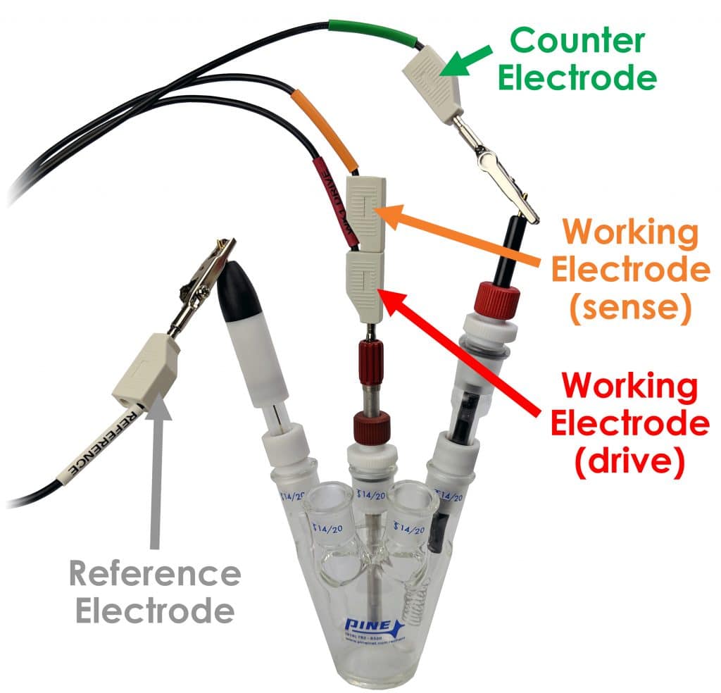
To drive current between the working and counter electrodes, the RED lead (working electrode drive) is connected to the working electrode, and the GREEN lead (counter electrode drive) is connected to the counter electrode. To measure potential between the working and reference electrodes, the ORANGE lead (working electrode sense) is also connected to the working electrode, and the WHITE lead (reference electrode sense) is connected to the reference electrode (see Figure 1).
Note that the three-electrode cell configuration requires both the RED and ORANGE leads (working electrode drive and sense) to be connected at a point very near the working electrode. An easy way to make this connection is to stack the banana plugs for the RED and ORANGE leads together before connecting to the working electrode (see Figure 2). Both of these leads must be connected to the working electrode for the potentiostat to properly control the electrochemical cell.


