1. What is a Potentiostat?
A potentiostat is an analytical instrument designed to control the working electrode’s potential in a multiple electrode electrochemical cell. The potentiostat contains many internal circuits that allow it to function in this capacity. The circuits generate and measure potentials and currents. External wires in a cell cable connect the potentiostat circuit to the electrodes in the electrochemical cell. In a conventional three-electrode cell, the cell cable connects to the working, counter (auxiliary), and reference electrodes on one end and the potentiostat cell cable connector on the other end. The internal circuitry of the potentiostat controls the applied signal. In the case of potential controlled methods, for example, the working electrode’s potential is held with respect to the reference electrode. At the same time, current flows between working and counter electrodes. The potentiostat circuit design prevents all but a tiny current from flowing between the working and the high impedance reference electrode. While modern potentiostats are more complicated than can be explained in this article, a brief introduction to potentiostat circuitry will be discussed to help you understand how a potentiostat works.
1.1. Terminology
2. How does a Potentiostat work?
2.1. Operational Amplifiers (Op-Amps)
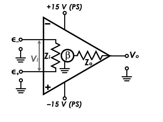
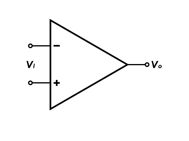
An operational amplifier, is an electronic circuit component powered by a DC voltage capable of amplifying an input voltage. Schematically, the op-amp symbol is a sideways triangle with inputs along the vertical line and the output at the point opposite the inputs (Figure 1). The voltage input to the op-amp is a differential value between two potential inputs, ∈+ (non-inverting input) and ∈– (inverting input), both of which are referenced to ground potential. The open loop gain of the amplifier is a scalar factor (β), and common amplifications are on the order of 105 – 106, dictated by the integrated circuit construction. The configuration of the external feedback circuitry can lower the gain to a user-selectable value. Some amplifiers have a fixed gain of 1, and only output the difference between the two input potentials. The output voltage, Vo , is equal to the product of the gain and the difference in the input voltages (Equation 1). In practice, several specific details of the op-amp circuit diagram are omitted for clarity (Figure 2). Notice in the simplified diagram, power supply voltages and circuit common (ground) are omitted and are assumed.

Figure 1: Circuit Diagram of an Operational Amplifier. In most op-amp circuit diagrams, the positive and negative Power Supply (+PS and -PS) potentials are assumed. Therefore, in circuit diagrams of op-amps, they are most often omitted.
Op-amps have several important characteristics, as follows:
- Small footprint, often measuring < 1 cm2
- Generally inexpensive and widely available
- Typically have large gains (β = 104 – 106)
- High input impedance (Zi ≥ 106 MΩ)
- Low output impedance (Zo ≤ 1 – 10 Ω)
- Ideally, zero output for zero input. In practice, there may be an offset voltage, which can be corrected (i.e., trimmed)
- Intrinsically have high bandwidth, allowing for a wide range of frequency input and output
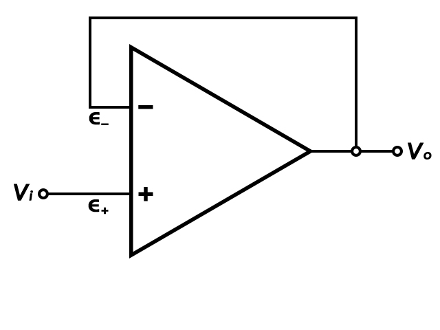
If an op-amp merely amplifies a voltage input, the voltage output can be driven too high. Due to the large gain, even a small differential voltage input (e.g., Vi = 0.001 V) can amplify the signal to a highly unusable (and possibly dangerous) voltage, limited by the amplifier supply voltage. To overcome this possibility, the output signal is routed back into the ∈– input, which creates a feedback loop. When an op-amp uses feedback, it forces ∈– to equal ∈+. This circuit is called a voltage follower (Figure 3). In the voltage follower circuit, if ∈+ input increases, so does ∈–. Since ∈– and Vo are tied together, Vo follows ∈+. Vi = Vo, thus the reduced gain, β, is 1.
2.2. The Potentiostat Circuit Diagram
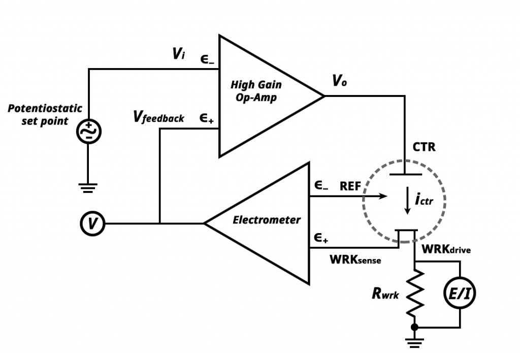
By understanding how an operational amplifier works we can describe how a potentiostat functions based on the figure below.
2.3. Other Electronic Components
3. Related Video
The following YouTube video can be found on the Pine Research YouTube channel. The video covers the same content in addition to walking through potentiostat operation during an electrochemistry experiment.


